 Back
Back
Detecting Hardware Vulnerabilities with IoT Penetration Testing
Welcome to a new series of DirectDefense blog posts about hardware and IoT penetration testing! The goal of this 101 series is to shed light on common hardware I/O interfaces, associated protocols, and the multitude of vulnerabilities that can arise when they are left unprotected. While hardware reconnaissance will be briefly discussed, this particular article will focus on Universal Asynchronous Receiver/Transmitters (UART).
Assess the Hardware Before the Test
Before diving into any hardware assessment, it can be very useful to do some background research for documentation, data sheets, specs, or architecture diagrams. Keep in mind that for some devices, this information isn’t publicly available, if available at all. In any situation, it is important to physically verify connections and signals.
In general, we are most interested in the following types of components on a Printed Circuit Board (PCB):
- Primary System on Chip (SoC)
- Debug interfaces and test pads
- External Memory/embedded Multi-Media Card (eMMC)
- Peripherals and Secondary SoCs
- Data buses between ICs
Even if you aren’t sure what to look for, oftentimes an easy win is to identify the manufacturing numbers printed on the surface of each Integrated Circuit (IC), then search the internet for public information. Information can be gleaned from public sources based on the Federal Communications Commission (FCC) IDs, from public marketing materials, or public online forums. The data sheet for an IC will have the most in-depth detail, and usually contains all technical low-level information for developers and system engineers.
Often, a target may have SoCs with many Input/Output (IO) capabilities such as U(S)ART, I2C, SPI, USB, GPIO, or JTAG. There are two main considerations when physically profiling a SoC:
- What hardware I/O interfaces are available?
- Has the firmware been programmed to enable or disable those interfaces? And if so, how has it been programmed?
It is very common for a hardware I/O interface to be physically connectable on a SoC, but logically disabled through one-time writeable programmable fuses, soft disabling in the firmware, or an application/operating system (OS) configuration.
Furthermore, the final or release version of a PCB design often disables or removes physical connections to debug interfaces or data buses. However, if left enabled in firmware, attackers may be able to directly interface with the SoC through exposed pins, or even via advanced techniques involving “decapping” or removing layers of the chip, akin to major surgery. Regardless of the target, it is crucial to verify both the physical layout and what is actually logically enabled and used.
Examining an ASUS RT-AC68U
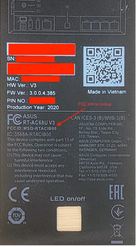
Following some of our own advice above, let’s take a look at an ASUS RT-AC68U router. First, even without opening the enclosure, we can glean some information from the sticker on the back, including the very useful FCCID:
Now, let’s look up that FCC ID using a public site that aggregates FCC filing info. There is a lot of data, including internal photographs and chip identification.
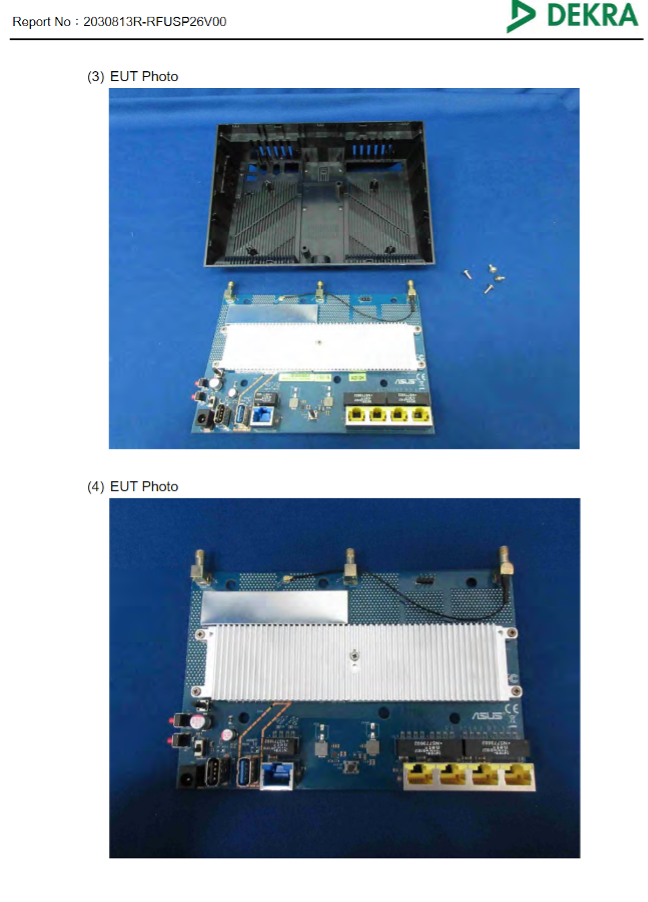
Without even needing to take apart the device, we can already get a good list of interesting components, such as:
- Primary SoC: Broadwell dual core 1ghz BCM4708C0
- External storage: 256MB Nanya 1945 NT5CC128M16JR-EK
- External RAM: 256MB Macronix MXIC MX30LF10189C-TI
- Wi-Fi 2.4/5GHZ chips: Broadcom BCM4360
Although the data sheet for the BCM4708x series wasn’t available at the time of this writing, we did find some marketing material describing the SoC’s features.
One particularly helpful image shows a visual layout of the SoC:
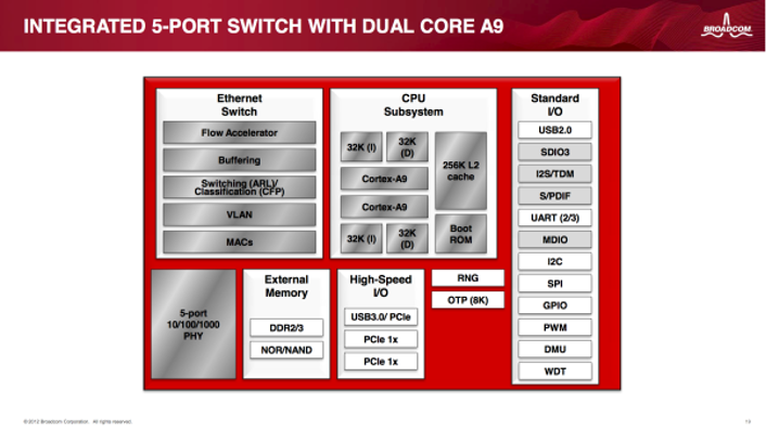
Per the high-level diagram above, we can see that the primary SoC supports a number of I/O protocols, including UART. We also know that it is using the external RAM and ROM because there are discreet devices for those purposes attached to it on the PCB.
Let’s take a closer look at a particularly interesting feature in the upper right hand of the board. There is a 4-pin header (J3) with pins VCC, TX, RX, and GND:
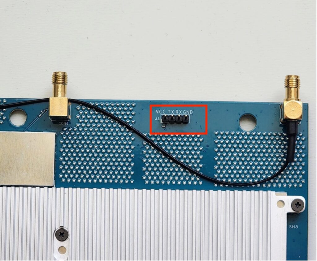
For an experienced IoT penetration tester, this feature would strongly suggest a debug interface over the UART. But as previously mentioned, and as interesting as it may be, we have to validate whether it is enabled at all, if it really is a UART, and if any data or interaction is possible.
The UART interface
A UART is one of the simplest, most common hardware I/O interfaces and is found on almost every SoC sold today. UART interfaces allow two devices to transfer data back and forth using serial communication. The term “asynchronous” is key here, referring to the fact that a dedicated clock signal is not used to determine the frequency at which bits are transmitted and received. This frequency, also referred to as the baud rate (bits per second), must be configured ahead of time on each device, and must match exactly. An exception to this rule is a variation called USART, where the “S” stands for synchronous. In this case, an extra signal wire is used to synchronize via clock, but can usually be backward-compatible with asynchronous operation.
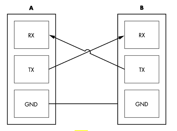
From a hardware perspective, this configuration means that UART interfaces typically have a dedicated data pin on which to transmit (TX) and a dedicated data pin on which to receive (RX). In order for two devices (A and B) to communicate with each other, these pins are physically connected – “crossed” with jumpers from TX[A]->RX[B] and RX[A]->TX[B]. An illustration of this connection from the Hardware Hackers Handbook is shown below:
Serial Communication
In serial communication, bits (0s and 1s) are represented with either a logic level low or a logic level high voltage. The logic level high voltage, as well as the threshold around it, varies significantly between TTL serial and implementations such as RS-232. In the UART example shown above, a common ground pin is used as 0V reference. Serial data transmitted on TX and received on RX operates between logic level low – 0V and a logic level high voltage of typically either 3.3V or 5V. Take for example the sequence below:
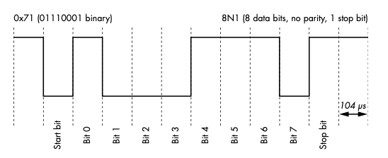
In the example above the line is held high until data is transmitted. Logic high represents a 0, and logic low represents a 1. The line is pulled low to represent a start bit (0), then 8 bits (1 byte) are sent. At the end of a byte, no parity (error checking) bit is sent but a stop bit of 1 is sent. By taking the inverse of the shortest “pulse”, such as the start bit (104 microseconds), we can calculate the baud rate in this case: 1/(104×10^9) = ~9600 bits/second.
For many UART implementations, typically 3 pins are all that is needed for communication. A 4th pin can be used to provide power to the target. The table below summarizes this information. It references a typical 4-pin header pinout for UART, which is also seen on our target:
| Pin | Label | Purpose | Note |
| 1 | VCC | 5V power | Can provide power to target, usually left disconnected while target is powered via AC/DC adapter. |
| 2 | TX | Transmit Data | Target’s send data pin (Connect to RX of other device for comms). |
| 3 | RX | Receive Data | Target’s receive data pin (Connect to TX of other device for comms). |
| 4 | GND | Ground | Common signal ground reference is key for two devices to distinguish between logic levels (0’s, 1’s) used in serial protocol. |
Useful Tools for Analyzing UART Communications
In order to proceed with analyzing UART communications, here are a few useful tools:
- Precision Screwdriver set – useful for disassembling devices with small, mixed fasteners.
- FTDI USB to TTL cable – needed for UART serial comms.
- Multimeter – highly recommended to verify connections, especially ground.
- Saleae Logic Analyzer – incredibly useful for signal analysis, but expensive.
Multimeter Analysis: Basic Testing for a UART Interface
Let’s do some basic testing with our meter.
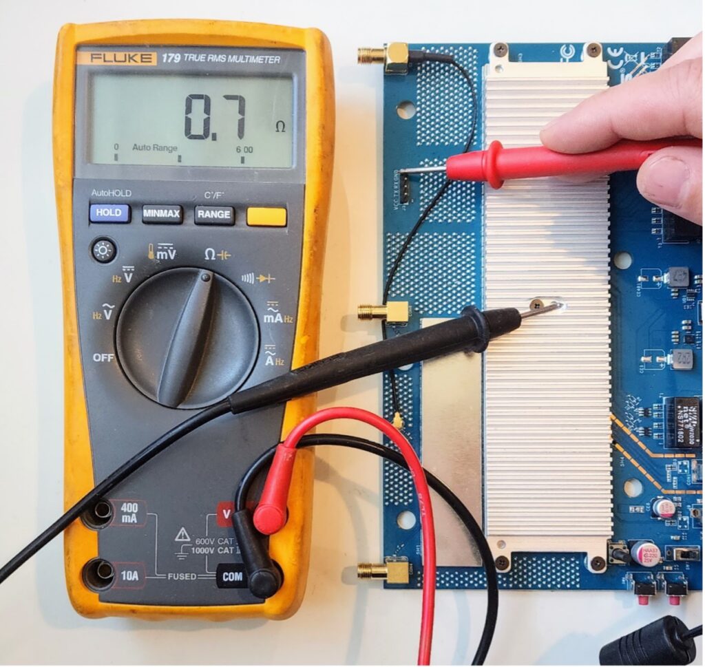
First, let’s confirm the ground pin. We can either use the continuity mode for an audible tone, or set our meter to measure resistance. The ground pin should be shorted (or nearly so on the readout) to a common ground point on the PCB. This can often be found on the shielding of ports, but keep in mind that some devices, such as PoE routers, may have an isolated ground. In this instance, the large passive heatsink is part of the ground on this device as shown in the image below:
As previously mentioned, the TX pin will be held at a logic level high voltage until data is transmitted (idle state). We can infer which pin is transmit by probing its voltage while the device powered on. Below shows a voltage read for the TX pin:
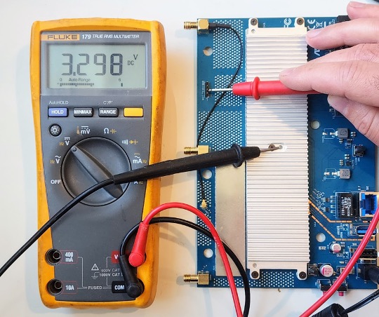
Based on the 3.3V, we can be reasonably sure this is the TX pin, using a logic level high voltage of 3.3V.
Saleae Logic Analyzer: Digging Into the UART Interface
Now that we have identified a suspected UART interface, we can investigate further with a Logic Analyzer. Even though we have a nice pin header and labels, we don’t always have this luxury. Approaching this situation from the perspective that the target interface is unknown, we will perform signal analysis on the TX and RX pins.
For demonstration purposes, we will be using a popular professional tool: Saleae Logic Pro 16, which is an expensive but invaluable tool for signal and protocol analysis. It can be used to reverse-engineer the implementation of a target even when little or no documentation is available. This device allows us to capture digital and analog signals at an extremely high sample rate. It also contains handy “analyzers” for decoding common protocols, such as asynchronous serial.
- Connect the target ground to any of the bottom row pins (all shorted internally to ground). If ground is not obviously labeled or broken out onto a header, it can be helpful to use a multimeter to test various points on the PCB chassis to find it. In this case, with a multimeter, it was found that the labeled GND pin is indeed connected to common ground on the PCB.
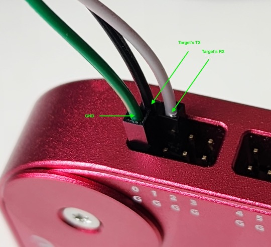
- Connect the target pin headers (TX, RX, etc.) to any of the 16 data channel pins on the Saleae. For demonstration purposes, we’ll connect the target’s TX to channel 0 and RX to channel 1 as shown below:
In the Saleae Logic2 software, we’ll need to configure the data channels to capture the pins we physically connected. The standard sample capture rate should be more than sufficient to capture the relatively slow baud rates on which serial operates.
Next, we can conduct a capture by pressing the play button. Once the capture has begun, the device should be powered on. In a brief five-second capture, we can immediately see some data was passed on channel 0 (target’s TX) as shown below:

The lack of data transmitted on Channel 1 (Target’s RX) is expected, since it is the channel on which the UART is expecting to receive data.
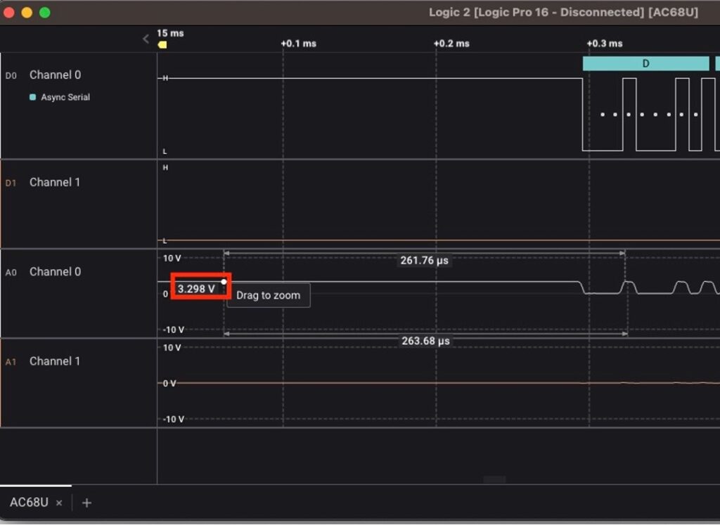
On Channel 0, note the presence of a digital square wave. If we zoom in on the corresponding raw analog component, we can see that the voltage is alternating between 0 and roughly 3.3V. It is also held high at 3.3V until data is transmitted:
Since we already highly suspect this is asynchronous serial communication, we can try a handy built-in feature of the Saleae Logic2 software – analyzers. Saleae has a built-in asynchronous serial decoder that can automatically parse captures, then decode data using a number of criteria from serial including baud rate, parity, and start and stop bits.
In most cases, the baud rate is all that needs to be set. As previously mentioned, we can determine the baud rate by taking the inverse of the smallest observed pulse:
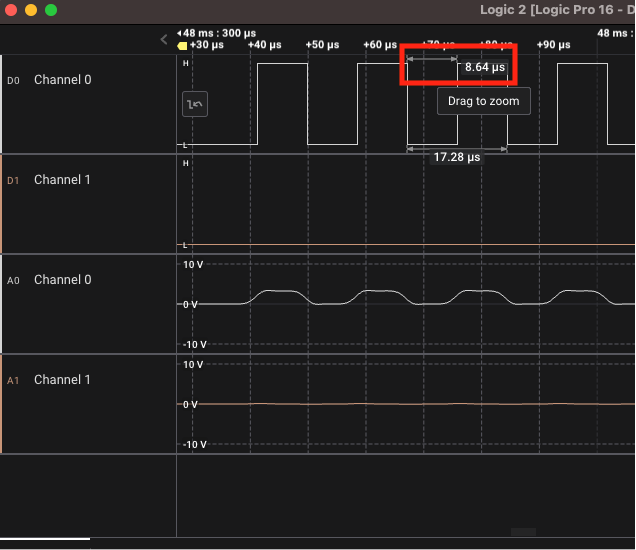
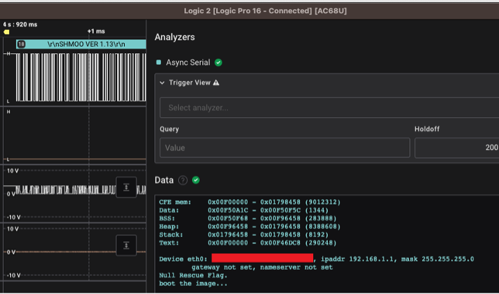
In this case, 1/(8.64×10^-6) = ~115200bits/second. After configuring the analyzer with this value, the result of the decoded serial as ASCII text can be seen in the pseudo-terminal of the screenshot below, as well as individual bytes from the capture:
FTDI Interaction with the UART
Now that we have confirmed the use of UART and decoded some of the output with the logic analyzer, let’s try to interact with it using our FTDI cable. This TTL to USB cable allows us to transmit data over serial using a TTY (Linux) or COM (Windows) interface. The following shows an example image of a TTL cable previously mentioned:
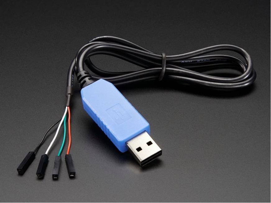
It should be noted that this TTL Cable operates only on logic levels 0/3.3V, while some UART’s operate on 0/5V. The pin configuration of this device is as follows:
| Wire Color | Purpose | Note |
| Red | 5V power | Can provide power to target, usually left disconnected while target is powered via AC/DC adapter. |
| Green | Transmit Data | FTDI’s send data pin (Connect to RX of other device for comms). |
| White | Receive Data | FTDI’s receive data pin (Connect to TX of other device for comms). |
| Black | Ground | Common signal ground reference is key for two devices to distinguish between logic levels (0’s, 1’s) used in serial protocol. |
Connect the RX and TX pins “crossed” to the target as previously explained in the UART interface section:
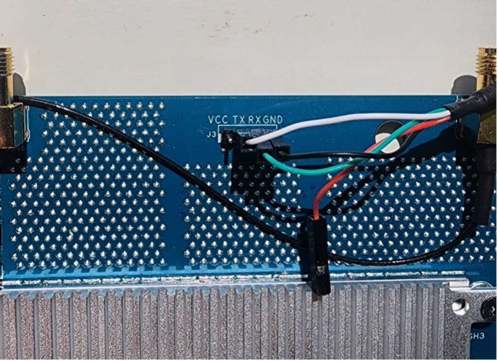
Connect the ground wire to the target’s ground pin.
Next, establish a connection to the USB device so we can send/receive serial. For this example, we’ll use the application “screen” on MacOS, specifying the interface and baud rate 115200:
➜  ~ ls /dev/tty.usbserial-0001

➜  ~ screen /dev/tty.usbserial-0001 115200
Next, power on the device. Note that data is streamed to the terminal:
Info: DDR frequency set from clkfreq=1000,*666*

robo_eee_advertise_init: GPHY0: EEE advertisement is disabled

robo_eee_advertise_init: GPHY1: EEE advertisement is disabled

robo_eee_advertise_init: GPHY2: EEE advertisement is disabled

robo_eee_advertise_init: GPHY3: EEE advertisement is disabled

robo_eee_advertise_init: GPHY4: EEE advertisement is disabled

et0: Broadcom BCM47XX 10/100/1000 Mbps Ethernet Controller 7.14.164.303 (r666427)

CPU type 0x0: 1000MHz

Tot mem: 262144 KBytes

CFE mem:    0x00F00000 - 0x01798458 (9012312)

Data:       0x00F50A1C - 0x00F50F5C (1344)

BSS:        0x00F50F68 - 0x00F96458 (283888)

Heap:       0x00F96458 - 0x01796458 (8388608)

Stack:      0x01796458 - 0x01798458 (8192)

Text:       0x00F00000 - 0x00F46DC8 (290248)

Device eth0:  hwaddr DE-AD-BE-EE-FF-00, ipaddr 192.168.1.1, mask 255.255.255.0

        gateway not set, nameserver not set

Null Rescue Flag.

boot the image...
From the output, we can see that this UART is being used as a debug interface, streaming verbose boot data. The bootloader in use is CFE (a.k.a café). Once we let the device fully boot, we can see two interesting opportunities to interact: first, during the CFE initial boot; and second, when the device is fully booted, at which time we are provided a Linux shell.
Bootloader Access
If Ctrl-C is pressed during boot, we can break out of the normal boot process into an interactive shell as seen below:
CFE version 7.14.164.303 (r666427) based on BBP 1.0.37 for BCM947XX (32bit,SP,)

Build Date: Fri Sep 18 09:39:01 CST 2020 (defjovi@ubuntu-eva00)

Copyright (C) 2000-2008 Broadcom Corporation.

Init Arena

Init Devs.

Boot partition size = 262144(0x40000)

DDR Clock: 666 MHz

Info: DDR frequency set from clkfreq=1000,*666*

robo_eee_advertise_init: GPHY0: EEE advertisement is disabled

robo_eee_advertise_init: GPHY1: EEE advertisement is disabled

robo_eee_advertise_init: GPHY2: EEE advertisement is disabled

robo_eee_advertise_init: GPHY3: EEE advertisement is disabled

robo_eee_advertise_init: GPHY4: EEE advertisement is disabled

et0: Broadcom BCM47XX 10/100/1000 Mbps Ethernet Controller 7.14.164.303 (r666427)

CPU type 0x0: 1000MHz

Tot mem: 262144 KBytes

CFE mem:    0x00F00000 - 0x01798458 (9012312)

Data:       0x00F50A1C - 0x00F50F5C (1344)

BSS:        0x00F50F68 - 0x00F96458 (283888)

Heap:       0x00F96458 - 0x01796458 (8388608)

Stack:      0x01796458 - 0x01798458 (8192)

Text:       0x00F00000 - 0x00F46DC8 (290248)

Device eth0:  hwaddr DE-AD-BE-EE-FF-00, ipaddr 192.168.1.1, mask 255.255.255.0

        gateway not set, nameserver not set

Startup canceled

CFE> ^C

CFE> ^C

CFE> whoami

Invalid command: "whoami"

Available commands: nvram, reboot, flash, batch, go, boot, load, save, ping, arp, ifconfig, show, help

*** command status = -1

CFE> ifconfig

Device eth0:  hwaddr DE-AD-BE-EE-FF-00, ipaddr 192.168.1.1, mask 255.255.255.0

        gateway not set, nameserver not set

*** command status = 0
By interrupting the boot process and dropping into a bootloader shell, we can potentially bypass the restrictions of the Linux kernel and user space. At this point, we can likely load our own firmware, overwrite the existing, or pass kernel arguments to bypass user space restrictions.
Default Login
If we allow the boot process to continue uninterrupted, there is also an opportunity to interrupt the login process by pressing the “Enter” key during the Init process:
VFS: Mounted root (squashfs filesystem) readonly on device 31:3.
devtmpfs: mounted
Freeing init memory: 212K
init_main start.
1: set_action 0


Hit ENTER for console...
(none) login:
The login process is also available once fully booted:
RT-AC68U-9FB8 login: admin

Password:

ASUSWRT-Merlin RT-AC68U 386.9_0 Fri Jan  6 20:03:03 UTC 2023

admin@RT-AC68U-9FB8:/tmp/home/root#
Note that on this target, the default administrative password had been changed to a 16-character, randomly-generated string with lowercase, uppercase, special characters, and numbers. However, when attempting to log in with the default username and password, it was successful.
(none) login: admin
Password:
ASUSWRT-Merlin RT-AC68U 386.9_0 Fri Jan  6 20:03:03 UTC 2023
Jan  1 00:00:42 login[43]: root login on 'console'
admin@(none):/tmp/home/root# ls
admin@(none):/tmp/home/root# cd /
admin@(none):/# ls
bin      cifs2    etc      jffs     media    mnt      proc     root     sys      tmp      var
cifs1    dev      home     lib      mmc      opt      rom      sbin     sysroot  usr      www
Upon further investigation, the default Linux user and password (admin, admin) had not been modified.
admin@(none):/# cat /etc/shadow
admin:$1$.6mJPFgR$PjXNkooPzkKT2s6yDKqL70:0:0:99999:7:0:0:
nas:*:0:0:99999:7:0:0:
nobody:*:0:0:99999:7:0:0:
tor:*:0:0:99999:7:0:0:
admin@(none):/# openssl passwd -1 -salt .6mJPFgR admin
$1$.6mJPFgR$PjXNkooPzkKT2s6yDKqL70
Successful IoT Penetration of a UART
As we have seen in this article, it is often possible to get a low-level debug shell with bootloader, elevated, or full administrative permissions via UART.
However, problems that can arise range in severity from non-interactive logs that dump verbose data during boot to full system compromise via interactive shells. In general, hardware I/O interfaces are often left unprotected for recovery or debug purposes.
With the access we gained through the bootloader or shell, we can conduct further analysis of the filesystem, applications, and shared libraries. Gaining shell access is typically a crucial starting point for conducting further penetration testing, and is often a primary objective for attackers.
If you enjoyed this article, check out our other blog posts.
 08.24.23